Worm & Gear Rolling Process

Worm & Gear Rolling
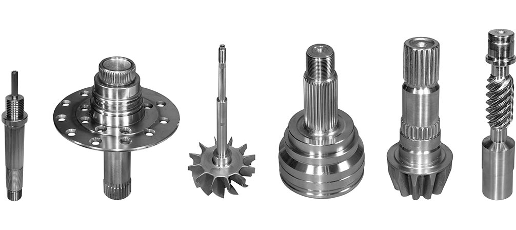
Kinefac rolling processes offer significant advantages over cutting operations with respect to accuracy, cycle time, surface quality, and material savings in the production of helical gears and worms for powertrain systems. Worms and gears are used in power transmission applications for speed reduction and directional changes. Motor shafts, reduction gears, conveyor drives, jacks, and hoists are common types of worm and gear components.
Worms are typically rolled on various components using infeed, throughfeed, plungefeed, and single revolution rolling. Gears are typically rolled using infeed and forced throughfeed rolling. Precision ANSI AGMA and DIN specification tolerance levels can be achieved by the Kinefac rolling process with respect to tooth profile error and lead error. AGMA Class 5 to 12 and DIN Class 8 or better is achievable by a controlled rolling process.
Benefits of Worm & Gear Rolling
|
|
Worm & Gear Geometry
Worm and gear forms consist of a profile geometry described by a straight or involute flank shape with crest flat, root flat, and radius transitions at fixed pitch spacing. The flank angle, or pressure angle when referring to worms and gears, is typically in the range of 10° to 25°. Worm profiles tend to have straight side flanks while gear profiles tend to have involute flanks. These profiles are matched with a mating form to achieve constant line contact when rotating in mesh.
Worm and gear profiles are generally deeper and can have proportionally thinner teeth compared to standard thread profiles of a similar pitch spacing. Most worms are single or multi-start with lead angles in the 30° range. Gears will have a specified number of teeth and can be straight with no helix angle, or non-parallel with a helix angle. Worm and gear forms are generally classified by diametral pitch which is the pitch diameter divided by the number of leads. Most worms and gears are rollable using the cylindrical die rolling process, but certain factors can limit the rollability of some profiles.
Kinefac Worm & Gear Rolling Process
| Key Requirements | Benefits |
|---|---|
| Stability, rigidity, and control accuracy of the rolling machine | Consistent pitch diameter |
| Accuracy and precision of the rolling dies | Profile and lead quality |
| Rotational synchronous accuracy of the rolling dies | Maintain die match with the work piece |
| Stability of the workpiece throughout the rolling process | Avoid drunken worm runout, and spacing error |
| Sufficient ratio of tooth depth to root diameter | Minimize risk of core failure during rolling |
| Size of the pre-roll blank diameter | Achieve correct fill of the worm major diameter |
| Controlled penetration speed of the rolling dies into the blank | Avoid over-fatigue and deep seams |
| Sufficient dwell time when dies have reached their final penetration position | Roundness calibration |
Superior Worm & Gear Rolling for Demanding Applications
Power transmissions
Automotive
Linear actuation
Industrial gearboxes
Aerospace
Electric motor shafts
Appliances
Conveyor drives
Hoists
Advanced Worm & Gear Rolling Control Features
POWERBOX machine structure
KINEFORM worm rolling dies
True Die Position system
Auto-Assist Die Matching
Reciprocating, dual-direction die rolling
Flat blade, roller blade, bushing, and center support tooling
KineGlide low friction rolling blades.
Servo blade automatic height control systems
Warm rolling systems

Advanced Worm & Gear Rolling Control Features
POWERBOX machine structure
KINEFORM worn rolling dies
True Die Position system
Auto-Assist Die Matching
Reciprocating, dual-direction die rolling
Flat blade, roller blade, bushing, and center support tooling
KineGlide low friction rolling blades.
Servo blade automatic height control systems
Warm rolling systems