SINGLE-POINT vs TWO-POINT COILING
Single-point deflection coiling is the more popular type of deflection coiling used in the United States. The tooling consists of final guides, a forming arbor, a single coiling point, a pitch tool and a cutter. The arbor acts as an anvil around which the wire is bent/deflected to achieve the desired coil diameter.
Two-point deflection coiling is the second most popular type of deflection coiling. It is more commonly used in Europe. The tooling for two-point coiling consists of final guides, two coiling points, a pitch tool, a cutter arbor and a cutter. The final guide and two coiling points create the three-point bending that permanently forms the wire into the spring shape.
Single-Point Coiling
Single-point coiling is a widely favored method for deflection coiling, known for its ease of set-up in creating various types of springs.
This process employs a specialized set of tooling which includes a final guide, forming arbor, single coiling point, pitch tool and cutter, each playing a specific role in the coiling operation.
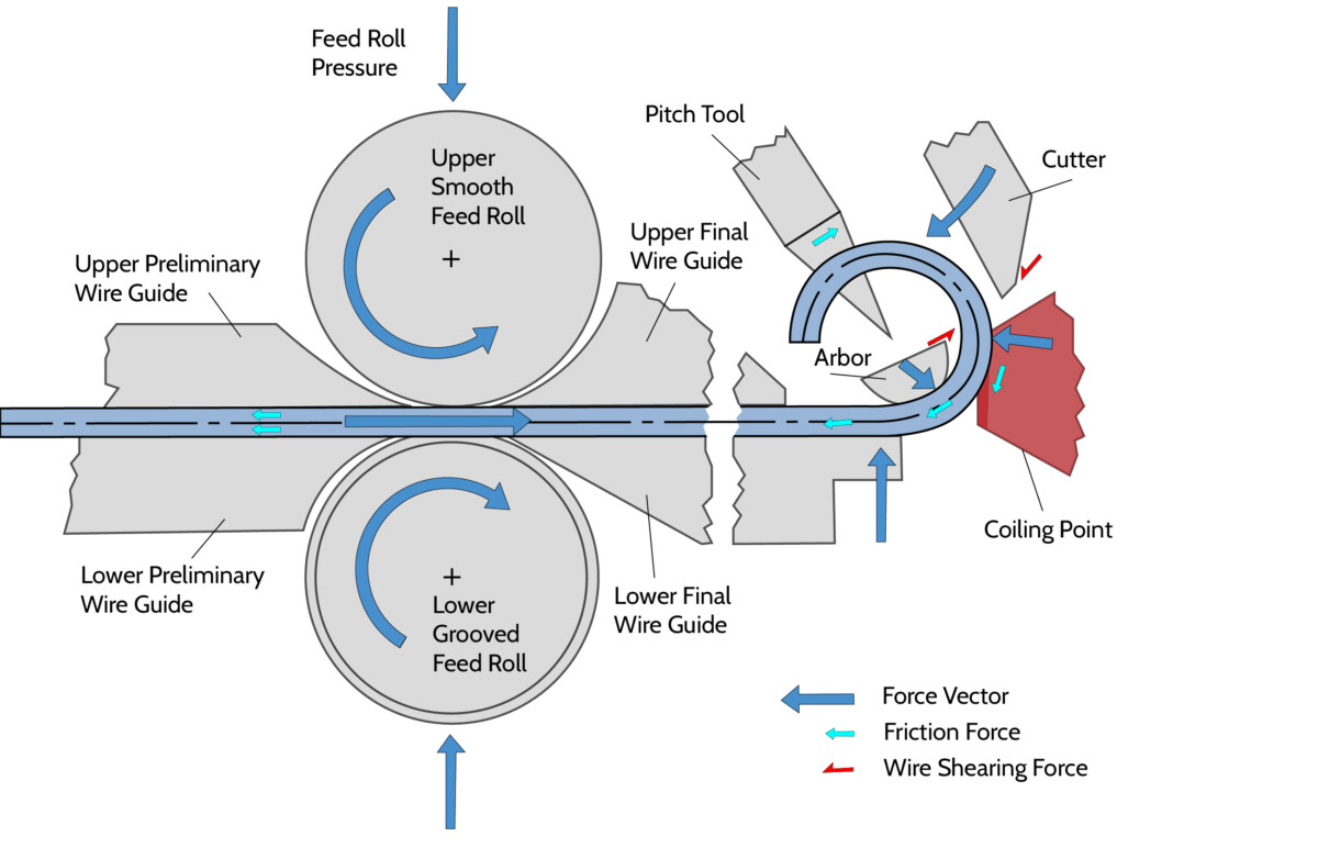
Figure A: Single-point deflection coiling
As shown in Figure A, the single coiling point holds the wire against the arbor resulting in three-point bending between the lower guide, arbor and the coiling point. The magnitude of bending induces enough plastic strain to permanently form the wire into the desired coil size. The coil diameter is adjusted by increasing or decreasing the amount of bend radius which is induced. This is achieved by moving the coiling point toward or away from the arbor centerline. A groove in the coiling point is matched to the wire size to control the wire as it feeds through the tooling.
A pitch tool controls the spacing between the turns of the coil. As the wire exits the coiling point it slides against the face of the pitch tool. The pitch tool is pushed against the wire to create the desired degree of inter-coil spacing or coil stiffness when there is no spacing. The pushing action induces enough plastic strain about the wire axis to permanently form the coil pitch spacing or set the stiffness. Compression springs require spacing between turns to allow the spring to compress and generate a resisting mechanical force. Conversely, extension springs are produced with no pitch spacing between turns so they can apply a resisting mechanical force when stretched. Torsion springs can be produced with or without pitch spacing to achieve the desired resisting torque and is mostly independent of pitch spacing.
A cutter tool trims the wire across the top shearing surface of the arbor to create coils and springs of discrete lengths. Enough wire is fed through the tooling to create the desired length of spring. The cutter then shears the wire cleanly across the top of the arbor tool surface with little to no resulting burr. In single-point coiling the limiting factor for small coil diameter-to-wire size ratios (Index) is typically the size of the arbor. If the arbor cross section is too small, it will not be able to withstand the cutting forces.
Two-Point Coiling
Two-point coiling is the second most commonly used deflection coiling method. This technique distinguishes itself from the single-point coiling process through its unique set of tooling and the absence of a forming arbor.
The tooling in two-point coiling includes a final guide, pitch tool, cutting arbor, cutter and two coiling points, each playing a specific role in the coiling process.
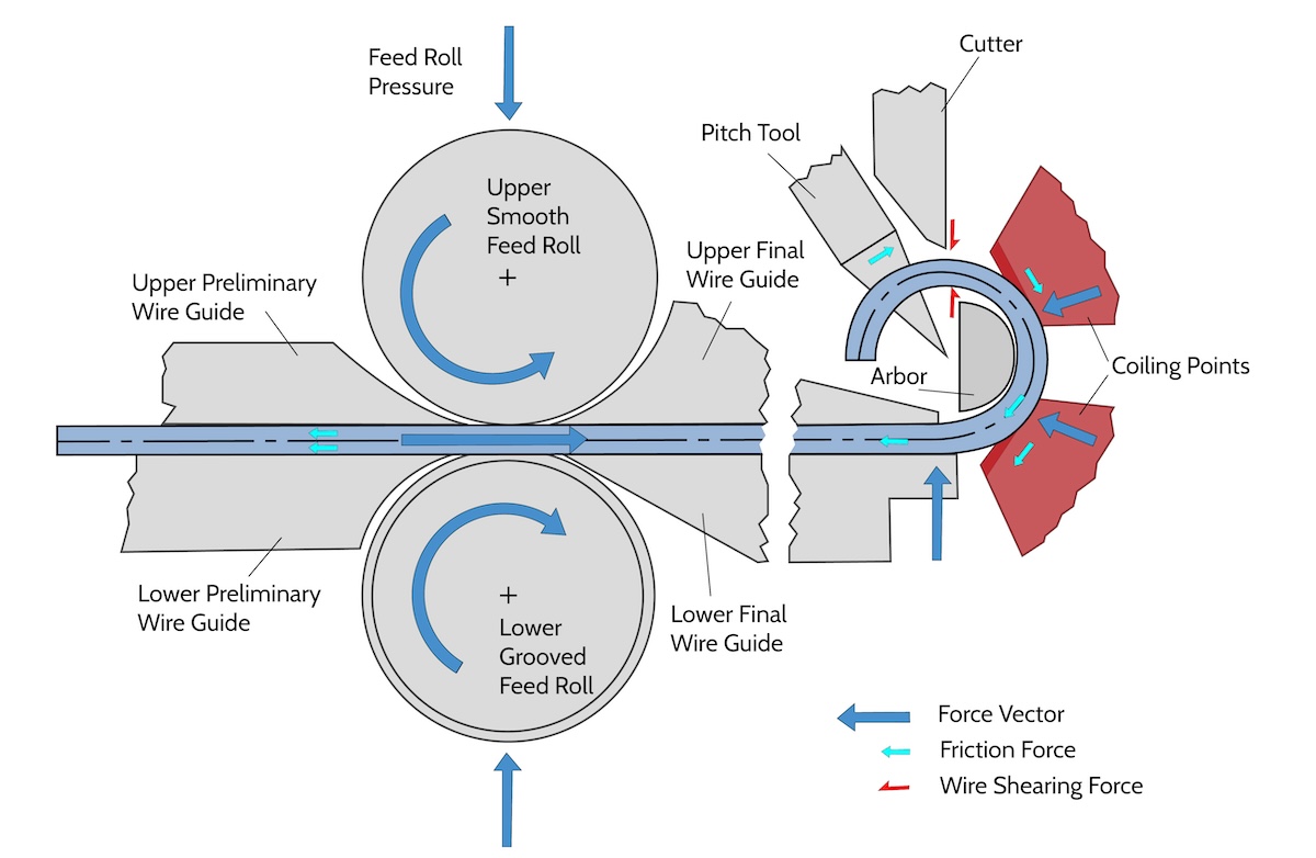
Figure B: Two-point deflection coiling
Unlike single-point coiling, a specifically sized forming arbor is not required for the bending. Instead, a cutting arbor is used to create a shear plane for the cutter tool to trim the springs into discrete lengths.
Since the tooling does not contact the inside diameter of the coil, it is usually possible to achieve smaller coil diameter-to-wire size ratios (Index) and lends itself to spring applications which require an untouched surface finish on the inside diameter. The limiting factor for small index coils is typically the size of the coiling point tools and how close they can be positioned next to one another. However, two-point coiling machine setups are more challenging due to the number of tooling alignments and adjustments required to make a spring of the desired shape and size.
A cutter tool trims the wire across the face of the cutting arbor to create coils and springs of discrete lengths. Enough wire is fed through the tooling to create the desired length of spring. The cutter then shears the wire cleanly across the cutting arbor tool surface with little to no resulting burr. Since the cutting arbor is not used for forming, it can be bigger in cross section and can better withstand cutting forces.
explore KineCoil Systems

CNC 5 AXIS MICROCOILER™
Advanced High Precision, High Speed Coiling System for Medical, Electronic and Miniature Applications
CNC 5/6 AXIS KINECOILER™
Versatile High Precision, High Speed Coiling System with Single- or Two-Point Configurations and Bidirectional Wind for Industrial, Electronic and Medical Spring Applications
HIGH SPEED COILER SYSTEMS
Integrated Advanced Wire Control Features with an Innovative High Speed Feed System for Enhanced Accuracy and Efficiency